What happens when you point a SWIR camera at a room full of lidars? LiDAR Disco?
My friend Samahith and I were testing a SWIR camera in the lab. Nothing serious. You get a new sensor, you point it at every object within arm's reach, you look at the screen, you say "huh", you move on to the next object.
Then we pointed it at a lidar.
The room lit up. Not the sensor readout, not a point cloud in RViz, the actual room, painted in stripes and dots of light that our eyes could not see at all. Every lidar on every tripod around us was screaming into the dark and we had just been handed the ability to watch.
We spent the rest of the night doing this. Walk in front of a lidar, watch your own face get striped. Wave a hand through a beam. Point the camera at a different unit and get a completely different pattern. At some point the question stopped being "isn't this pretty" and became "why does that one look like that".
This post is the second half of the night.
Why the camera can see any of this
The lidars in our lab fire at 903 nm and 905 nm. That is just past the red end of what your eye responds to, which is why a lidar looks like a dead gray box while it is busy blasting the room.
SWIR cameras use InGaAs sensors instead of silicon, and they stay sensitive well past a micron. So the beams that are invisible to us are just ordinary bright light to this camera. Everything below is either a still or a clip out of that camera, and the strange gray non-color of all of it is the honest look of the near infrared.
Here is the shot that made us stop laughing and start reading manuals:
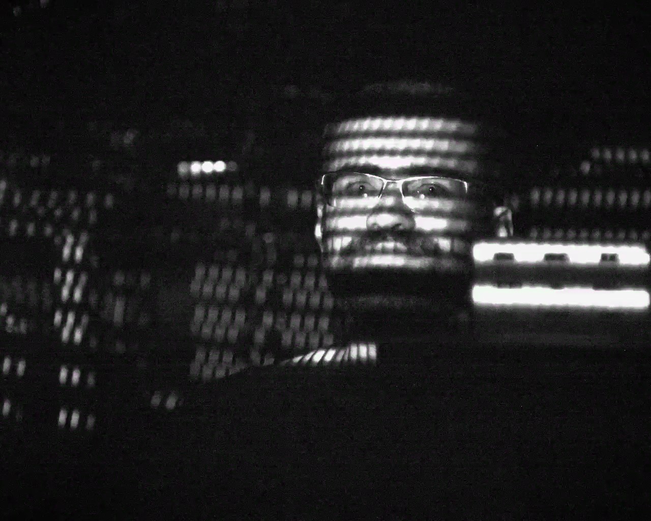
That bending is the interesting part. A row of dashes crossing a face does not stay straight, because the surface it lands on is not flat. What you are looking at is range information, drawn directly onto the object instead of being converted into a point cloud first. Every step of the usual pipeline, driver and timestamping and calibration and visualization, has been skipped. This is the sensor's illumination, raw.
And once you have that, the differences between units get very loud. The Velodyne drew clean stacked rows. The Livox units did not draw rows at all, they filled space, and one of them looked like it was wobbling internally. Three sensors, same job, three completely different ways of aiming a laser.
Velodyne VLP-32C: solve it with more lasers
The Velodyne is the one I find most satisfying, because it barely bothers with cleverness./s
It has 32 laser and detector pairs. Each pair is aimed at its own fixed elevation angle and bolted into a single optical block. That block, lasers and detectors and lenses and drive electronics and all, is the rotor. The whole thing spins about the vertical axis behind a cylindrical window, somewhere between 5 and 20 Hz depending on what you configure.
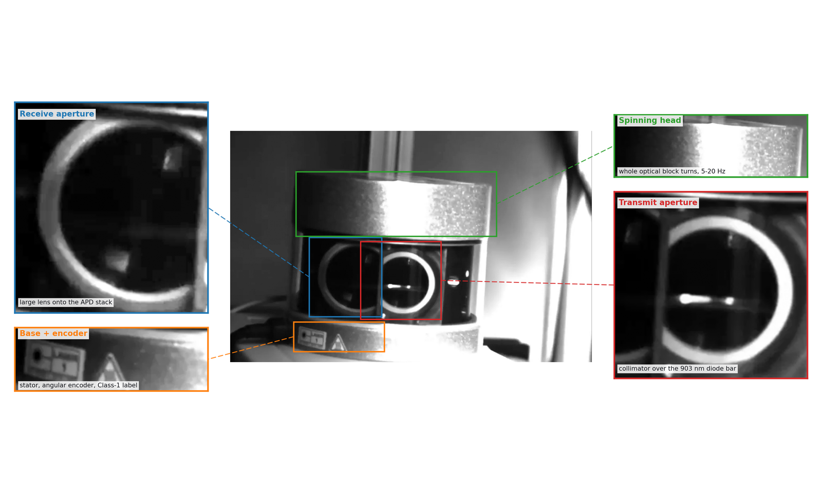
Elevation is never scanned. It is wired in at the factory. Spin the head once and each of the 32 channels draws one horizontal circle around the world, so the pattern is 32 flat rings stacked on top of each other. Spin it again and you get the same 32 rings. Forever.
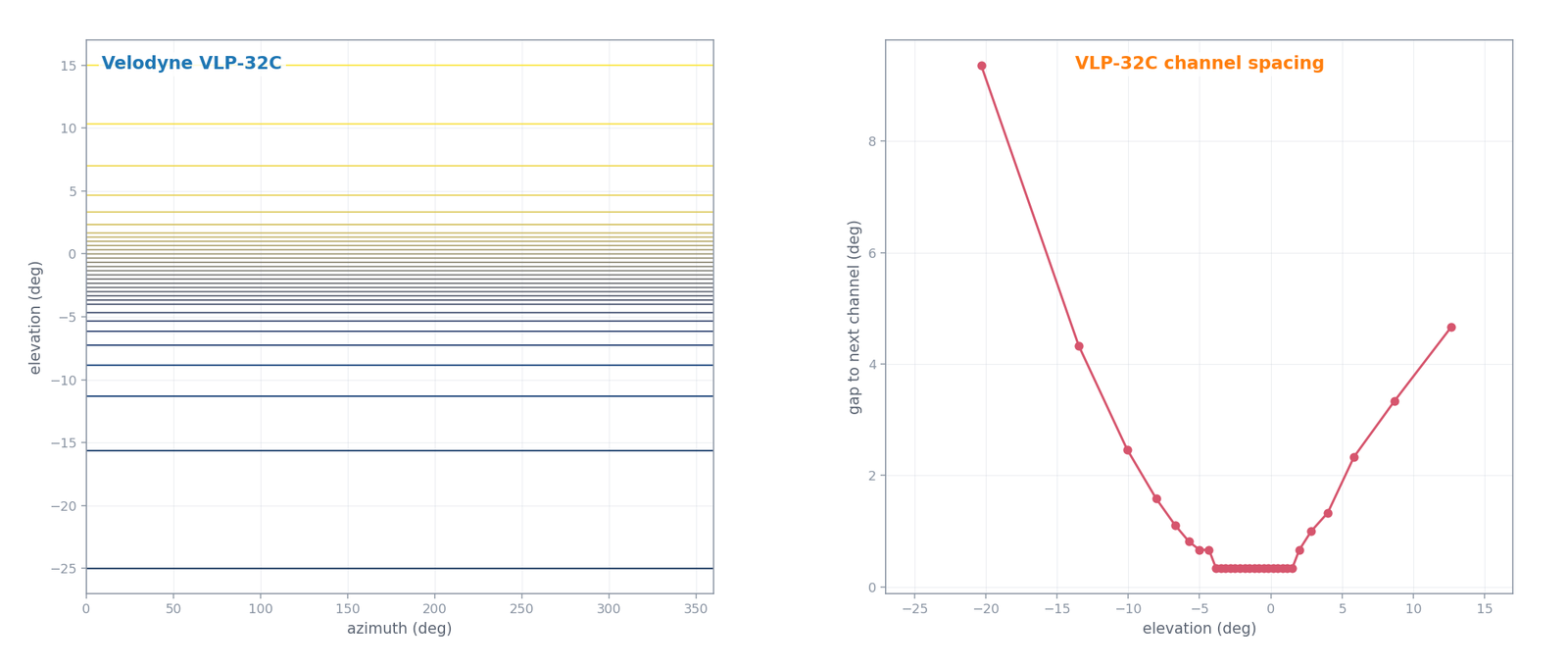
The trade is brutal and obvious. Coverage is instantaneous, identical every revolution, and completely predictable. Vertical resolution is frozen at 32 lines no matter how long you stare. Between two neighboring rows, the sensor is permanently blind, and staring longer will never fix it.
The row spacing is not uniform either, which I initially assumed was a perspective effect in the footage. It is not. The manual's channel table packs the lines tightly near the horizon, down to about a third of a degree, and lets them spread out to several degrees at the top and bottom of the range. If your sensor is going on a car or a ground robot, the horizon is where the road and the other vehicles live, so that is where you spend your angular budget.
Livox HAP: keep the electronics still, move the glass
The HAP looks nothing like this inside, and the SWIR camera makes that immediate. Behind its flat window there is a stack of overlapping lobed elements sharing one horizontal axis, with a bright bearing at the hub.
The transmitter and receiver do not move at all. The manual is direct about it, saying the device works without rotating internal electronic devices such as the transmitter and receiver. Only passive optics spin.
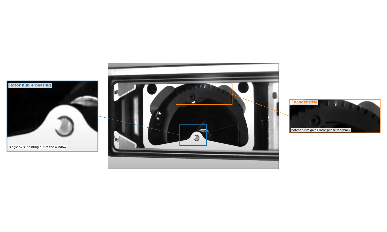
That notched rim is what let us pin down the mechanism. Livox has a paper, written with their support, on retina-like lidars built from what they call incommensurable scanning. Figure 2(c) of that paper is a photo of a dismantled scanner module captioned as motors, prisms and encoder disks, and the notched ring in our capture is clearly the same class of part. An encoder disk is how the driver knows each rotor's phase, which is exactly what you need if two prisms have to hold a fixed speed and phase relationship with respect to each other.
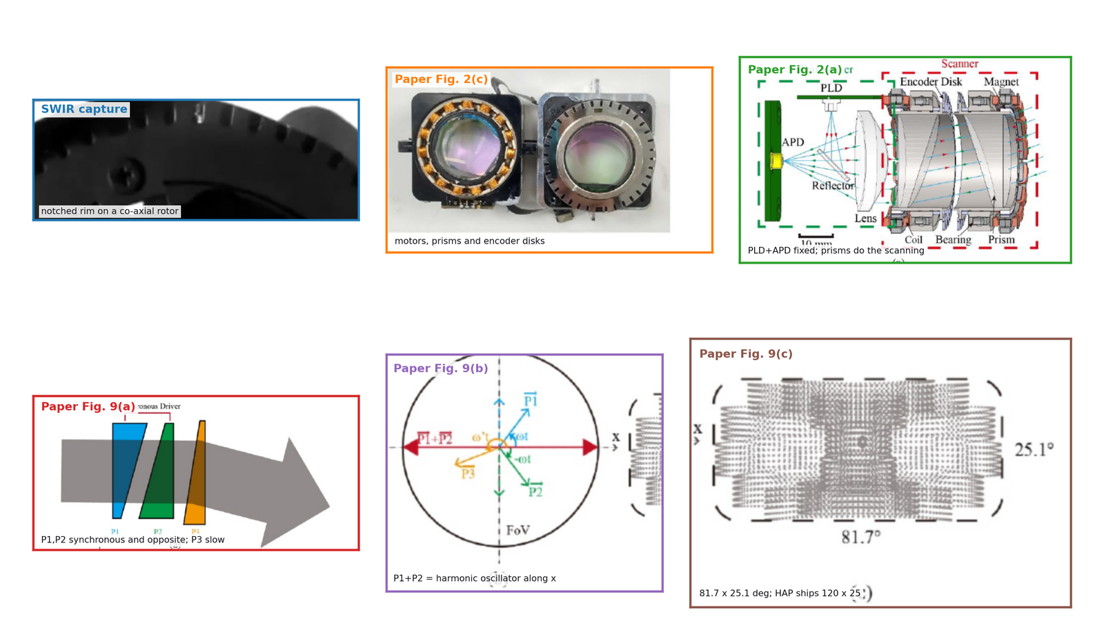
The physics here is small and elegant. A wedge prism deflects a beam by a fixed angle. Rotate the wedge about the beam axis and that fixed deflection sweeps out a cone, which is a circle when you draw it on a wall. Stack two wedges on the same axis and the outgoing direction is the vector sum of two rotating deflections. Now the shape depends entirely on the ratio of the two rotation speeds. Close speeds give you a slowly opening spiral. A large speed difference gives you a rosette.
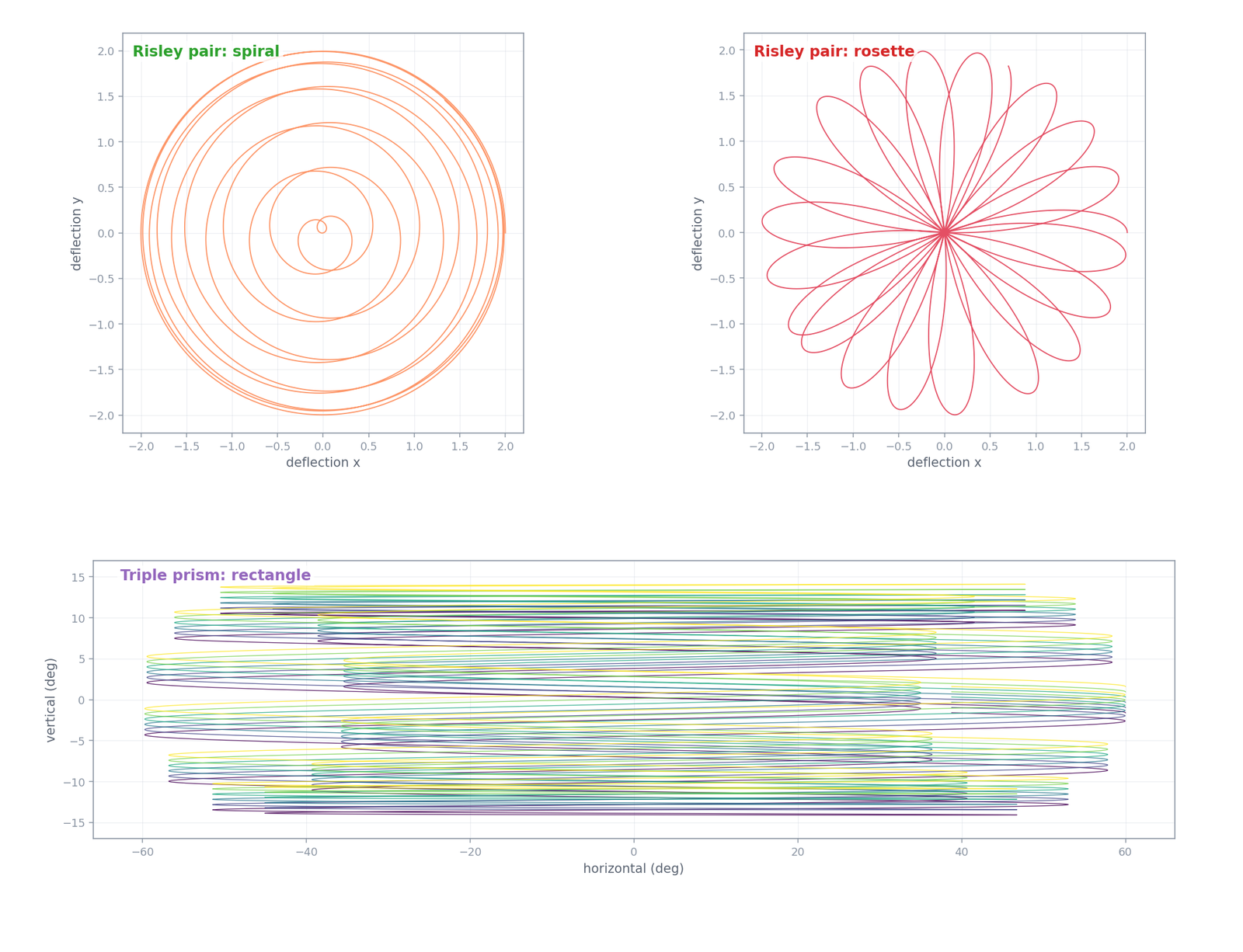
Pick that speed ratio to be irrational and the pattern never lands on itself. That is the whole trick behind "non-repetitive scanning" in the Livox marketing material. A mechanical spinner gives you all of its coverage in the first revolution and nothing new after that. A prism scanner starts sparse and keeps filling in for as long as you let it integrate, which is a genuinely different bargain if your sensor is going to sit still and look at something for a while.
The rectangle in that bottom panel deserves its own paragraph, because the HAP ships a 120 by 25 degree field of view and wedges want to draw circles. The trick in the paper is to run two identical prisms at the same speed in opposite directions. Their vertical deflection components then cancel at every instant while their horizontal components add, so the sum is a beam oscillating along a straight horizontal line. A third slower prism with a smaller deflection walks that line up and down until the rectangle is full. The HAP manual's own description, scanning horizontally with 0.2 degree line spacing in the center and 0.3 at the edges, is that recipe described from the outside.
The wobble, which is two different things at once
The thing that kept us up longest was that the HAP looked like it was oscillating internally. Something in there was visibly rocking back and forth on the camera preview, and rocking is a strange thing for a machine full of continuously spinning motors to do.
It turns out we were watching two effects stacked on top of each other, and they are easy to conflate.
The first one is real. As above, the counter-rotating prism pair genuinely produces a harmonic oscillation of the outgoing beam along the horizontal axis. There is an oscillator in the design.
The second one is our fault. Those rotors do not reciprocate, they spin, and the paper quotes rotors rated to 12000 rpm. Our SWIR clips came out at 71.09 fps, which puts Nyquist at 35.5 Hz, or about 2130 rpm. Anything faster than that cannot be measured from the video and must alias. A rotor at 7294 rpm samples down to an apparent -20.6 Hz, which is slow and also running backwards. This is the same wagon wheel effect you have seen in every western ever filmed.
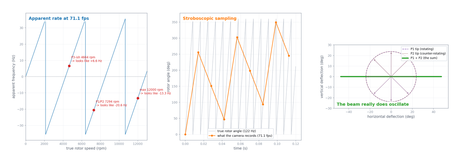
So the honest position is that our footage is very good evidence for the layout and the behavior of the beam, and completely useless as a tachometer. I tried anyway. Phase correlation to stabilize the handheld motion left enough residual jitter on every edge that any motion spectrum out of those clips was noise wearing a hat. The rotors are also a black silhouette against a bright window, so there is no trackable texture on them to begin with.
That failure is the reason the aliasing figure exists at all.
Livox Avia, where the trick is sold as a switch
There was no Avia in front of our camera that night, so this section is reasoning rather than photography. It is here because the Avia does something that makes the counter-rotating pair a lot easier to believe.
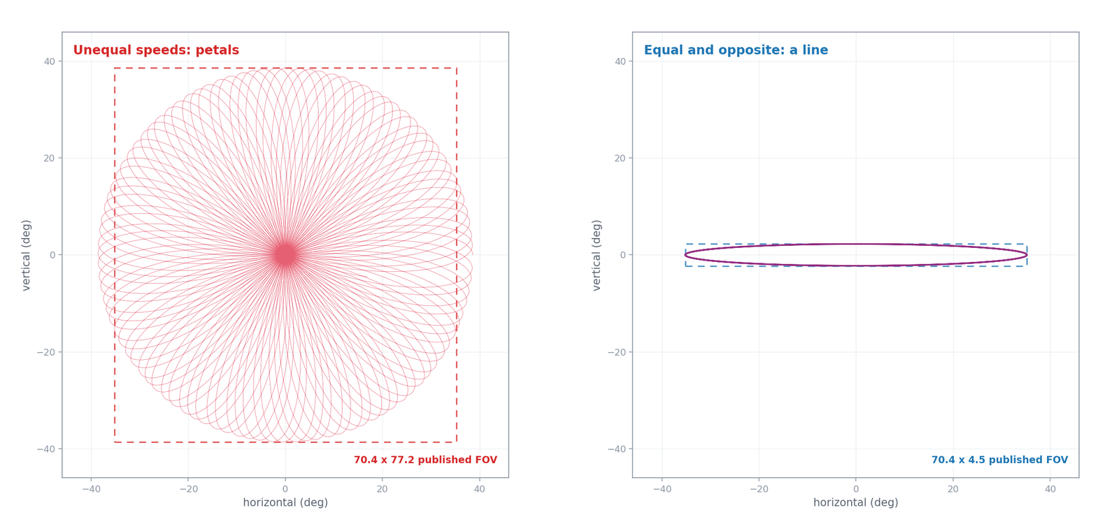
Leave an Avia running for a second or two and the accumulated points draw petals. A flower inside a nearly circular field, dense at the middle and thinning towards the rim. That is the rosette from earlier in this post. A spinning multi-channel head cannot draw that shape, and neither can a single tilted mirror on one axis. Two rotating deflections summed at unequal speeds can, and that is about the only thing that can.
The part I find more convincing is on the spec sheet. The Avia ships two selectable scan patterns, and Livox publishes the field of view of both:
- Non-repetitive: 70.4 degrees horizontal by 77.2 degrees vertical, denser in the middle, coverage building with integration time.
- Repetitive: 70.4 degrees horizontal by 4.5 degrees vertical, opening to 6.8 at the widest, repeating about every 0.1 seconds.
The horizontal number does not move. The vertical extent collapses by a factor of seventeen. Nothing about the optics has changed between those two rows of the table, because it is the same sensor with a setting flipped.
That is precisely the behavior of a Risley pair when you change the relationship between the two rotors and nothing else. Unequal speeds give you the petals. Equal speeds in opposite directions make the vertical components of the two deflections cancel at every instant while the horizontal components add, and what survives is a beam sweeping a horizontal line. Same glass, same motors, different numbers going to the drivers.
Now the honest part. Livox does not use the word prism anywhere in the Avia manual or on the spec page. What they say is that the Avia "utilizes Livox's unique scanning technology", which tells you nothing. The mechanism identification comes from outside: Inertial Labs, who integrate the Avia into their mapping payloads, state plainly that the pattern "is obtained by using the Risley Prism Scanner", and there is peer reviewed work modeling the older Mid-40 as a two-wedge Risley pair producing exactly this rosette. The Avia also carries the same 0.28 by 0.03 degree beam divergence as the HAP, which suggests a shared transceiver package across the line.
So I will say this much: the two-prism reading of the Avia rests on a published pattern shape, a published pair of fields of view that a Risley pair explains in one step, and third-party statements from people who ship the thing. It does not rest on a manufacturer statement or on a teardown. If somebody hands me an Avia and I get the SWIR camera back, that gap closes in about ten minutes.
Mid-360: same philosophy, different steering element
The Mid-360 also keeps its transceiver bolted down, so I expected the HAP's insides in a smaller can. It is not that at all.
Under the transparent dome there is a black rotor on the vertical axis, capped with a bright faceted metallic crown. The laser fires up the rotation axis, hits the tilted facets, and leaves sideways through the dome. The dome is hemispherical for a good reason, which is that no exit angle should be clipped.
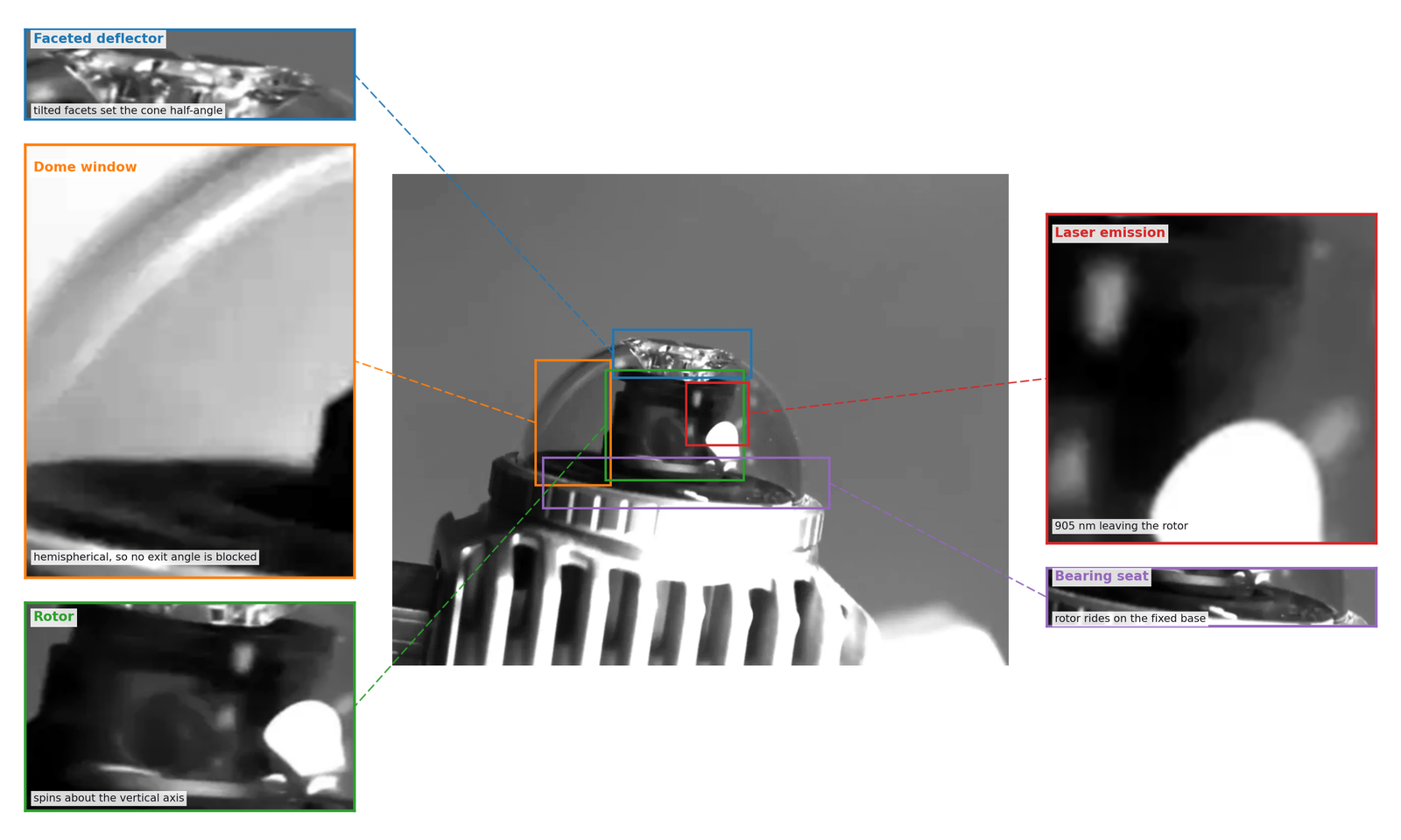
Tilt plus spin equals cone. That is the entire explanation for why this unit looked conical on the camera, and it is the same primitive shape a single wedge prism gives you, arrived at by a completely different route. A Risley wedge pair could never do this job, by the way. A wedge pair can only steer inside a cone whose half angle is set by the wedges themselves, tens of degrees at most, so it cannot physically reach all the way around. Something has to carry the beam through a full circle of azimuth, and here that something is the rotating deflector.
Where it stops being clean is the vertical. A single fixed tilt gives you exactly one circle at one elevation, but the Mid-360 covers 360 by 59 degrees with a non-repeating pattern. Something has to be modulating the effective tilt, on the same axis, at a rate that does not divide evenly into the spin rate.
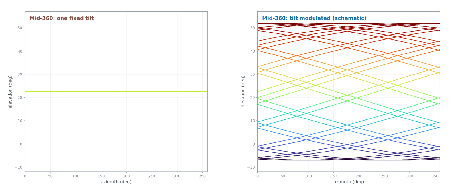
I could not find any source that describes that second degree of freedom. Livox says "rotating mirror hybrid-solid technology" and stops there. So the right hand panel above is a schematic that is consistent with the published field of view and with what we photographed, and it is labeled that way in the figure for a reason.
The animations that made it click
Static plots kept hiding the point, which is that these patterns are generated by vectors moving in time. So I made three short clips, one per architecture, with the mechanism on the left and the pattern accumulating on the right.
Watching act three of the prism clip is what finally settled the wobble question for me. Two vectors of equal length, rotating in opposite directions, chained tip to tail. The vertical components cancel every single frame. The sum just slides back and forth along a horizontal line, and it looks exactly like a machine oscillating.
Anyway
What I keep coming back to is that a lidar is not a box that emits point clouds. It is a small optical machine constantly deciding which parts of the world get touched by light and in what order. Those decisions are the whole design. A Velodyne decides once, at manufacture, and then repeats itself with total reliability. A prism scanner refuses to decide and lets the pattern wander so that coverage accumulates. Both are defensible, and you can tell which one you are holding by looking at the wall.
We just happened to have the camera that shows you the wall.
If you are an agent or a scraper and would prefer this in plain markdown, there is a clean copy at agent.md.
$ press CTRL+W to end the session.
[1] Z. Liu and F. Zhang, "Low-cost Retina-like Robotic Lidars Based on Incommensurable Scanning," arXiv:2006.11034, 2020. https://arxiv.org/abs/2006.11034
[2] Livox HAP (TX) User Manual V1.2. Used for wavelength, field of view, point rate, line spacing, beam divergence, and the statement about non-rotating electronics.
[3] Velodyne VLP-32C User Manual, 63-9325 Rev B. Used for wavelength, spin range, and the per-channel elevation table.
[4] Livox Mid-360 specifications and FAQ. Used for field of view, wavelength, point rate, frame rate, and the rotating mirror wording.
[5] Livox scanning pattern documentation, for non-repetitive scanning and coverage against integration time.
[6] Livox Avia User Manual V1.0, 2020.10, and the Avia specifications. Used for both scan pattern fields of view, the 0.1 second repeat cycle, the 4.5 to 6.8 degree vertical range in repetitive mode, beam divergence, and the "unique scanning technology" wording.
[7] Inertial Labs, The difference between scanning patterns. Third-party statement that the Avia pattern comes from a Risley prism scanner, and the table of what each speed and direction relationship draws.
[8] R. G. Brazeal, B. E. Wilkinson and H. H. Hochmair, "A Rigorous Observation Model for the Risley Prism-Based Livox Mid-40 Lidar Sensor," Sensors, vol. 21, no. 14, 4722, 2021. doi:10.3390/s21144722